Building an LED Matrix From Scratch: What I Built and What I Learned
Starting With an Idea and a Lot of LEDs
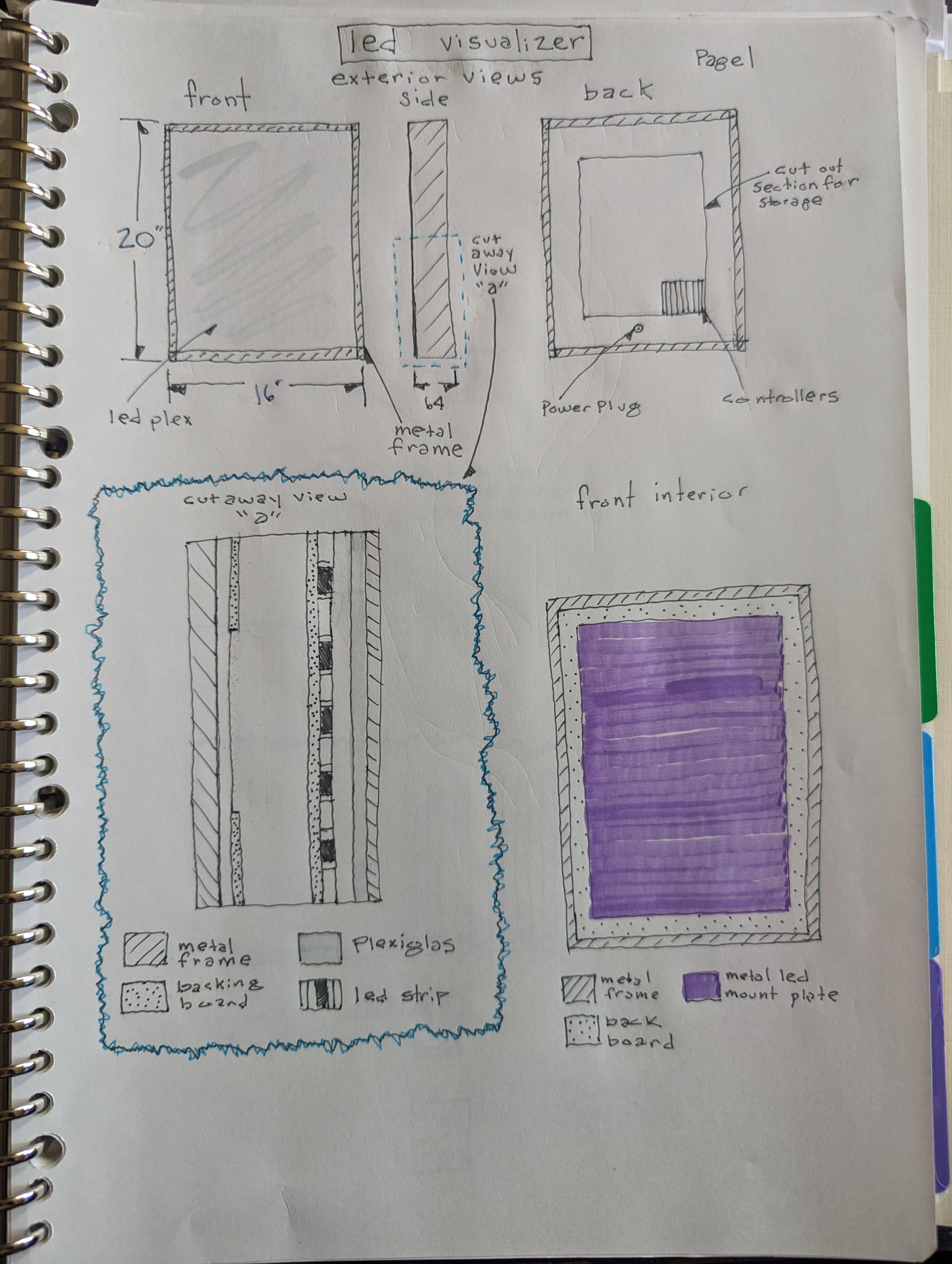
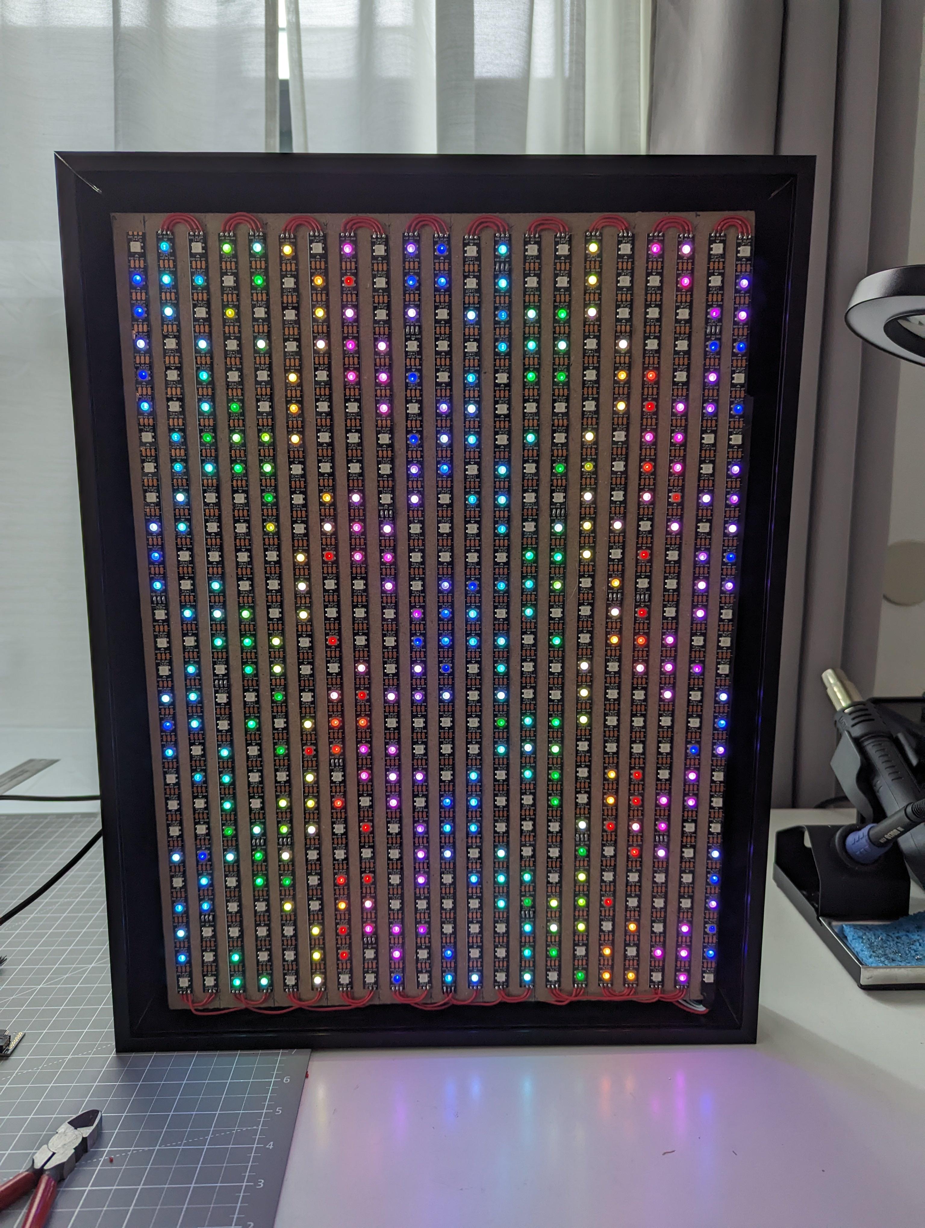
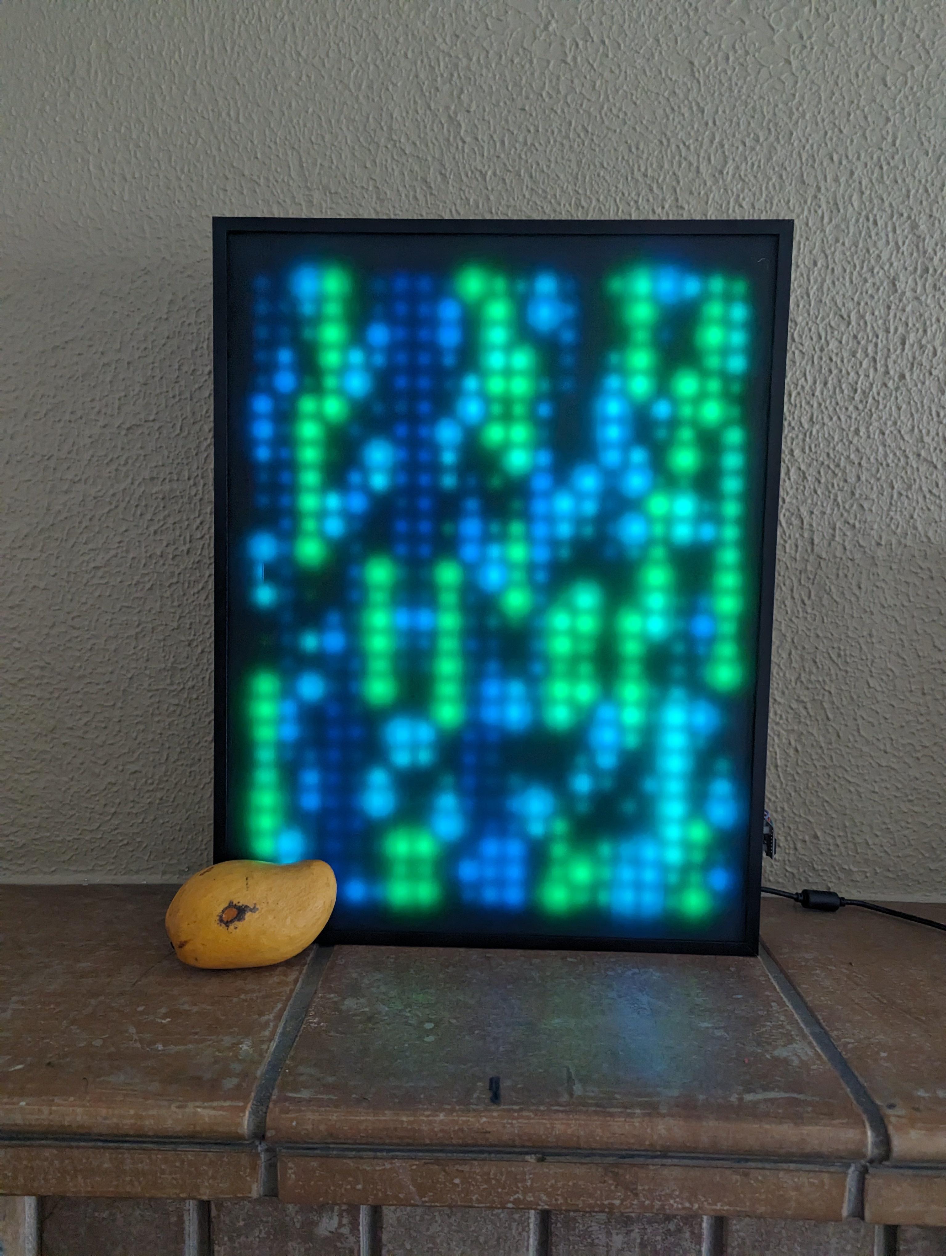
This project started with a simple idea. I wanted a large LED display that felt more alive than a static screen. The final result is a hand soldered LED matrix measuring roughly 20 by 16 inches. Visually, it behaves somewhat like a music visualizer, but instead of reacting only to sound, it became a general purpose canvas for experimenting with motion, patterns, and light.
From the beginning, I knew this would not be a plug and play build. I wanted to understand how everything worked at a practical level, from power delivery to data flow, even if that meant things would take longer or break along the way.
Learning the Hardware Through Trial and Error
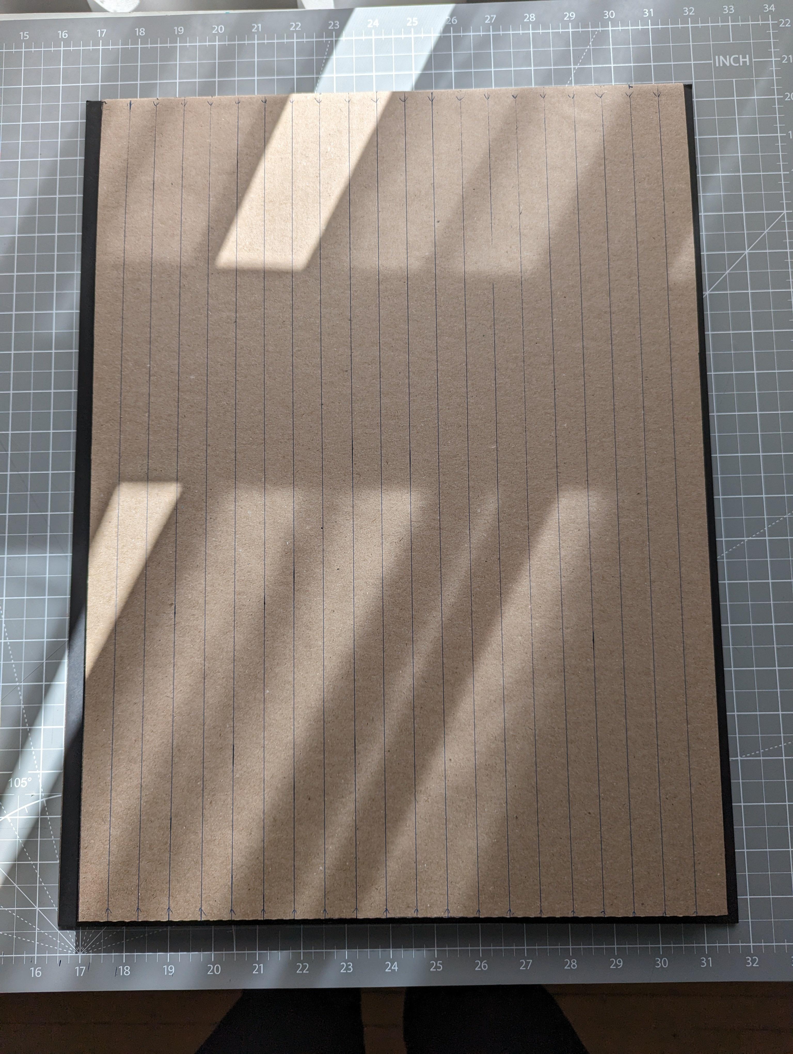
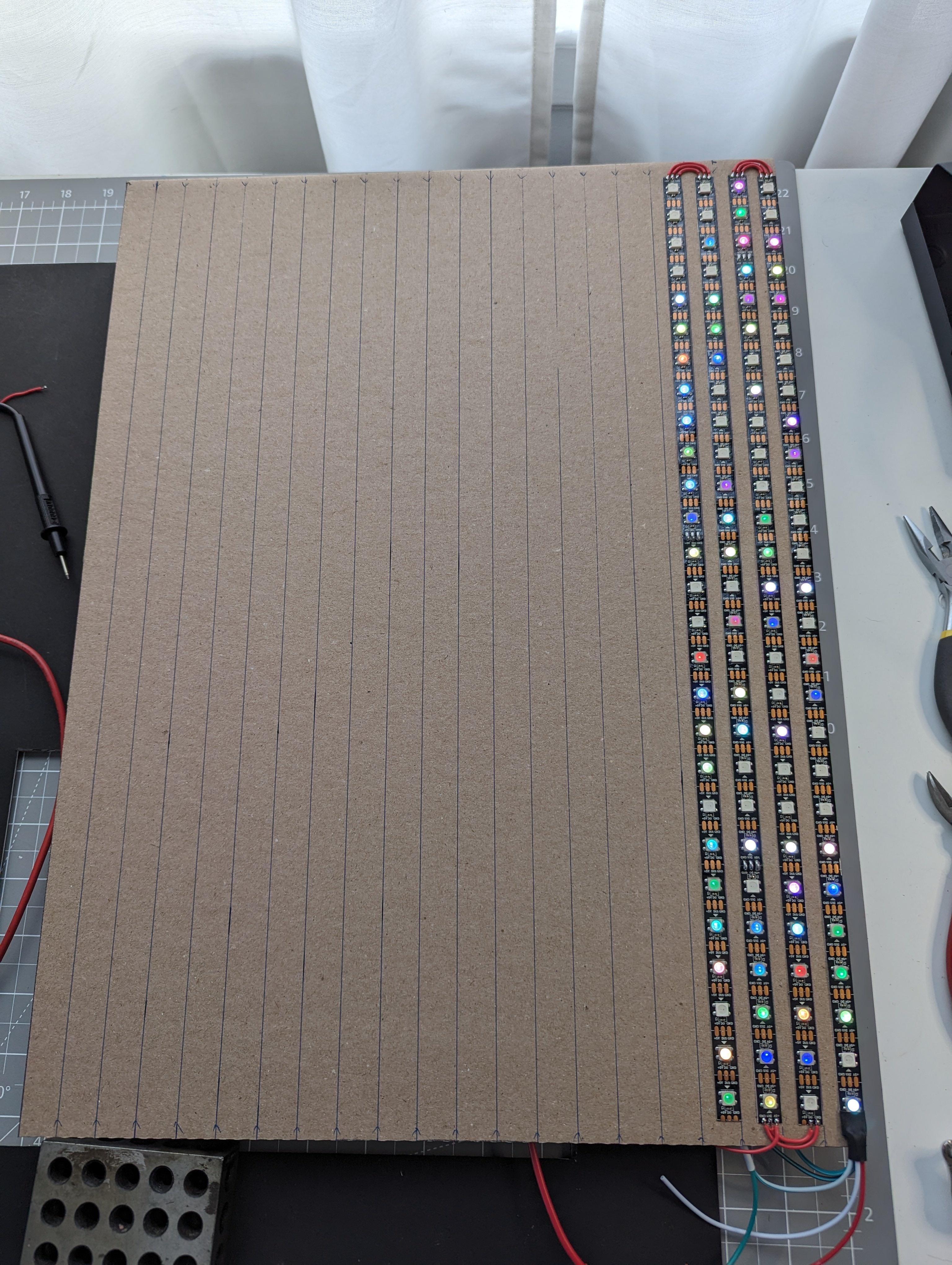
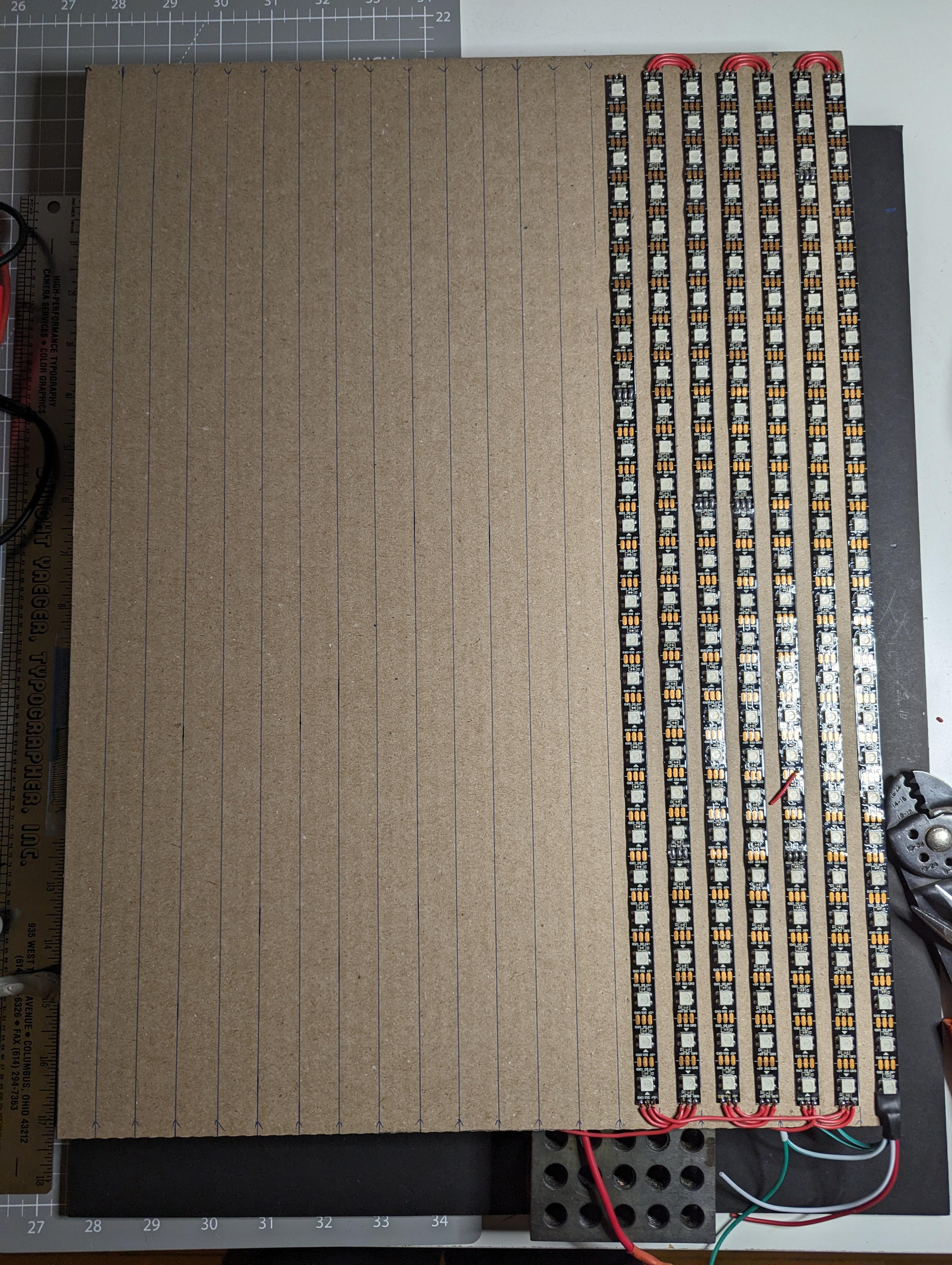
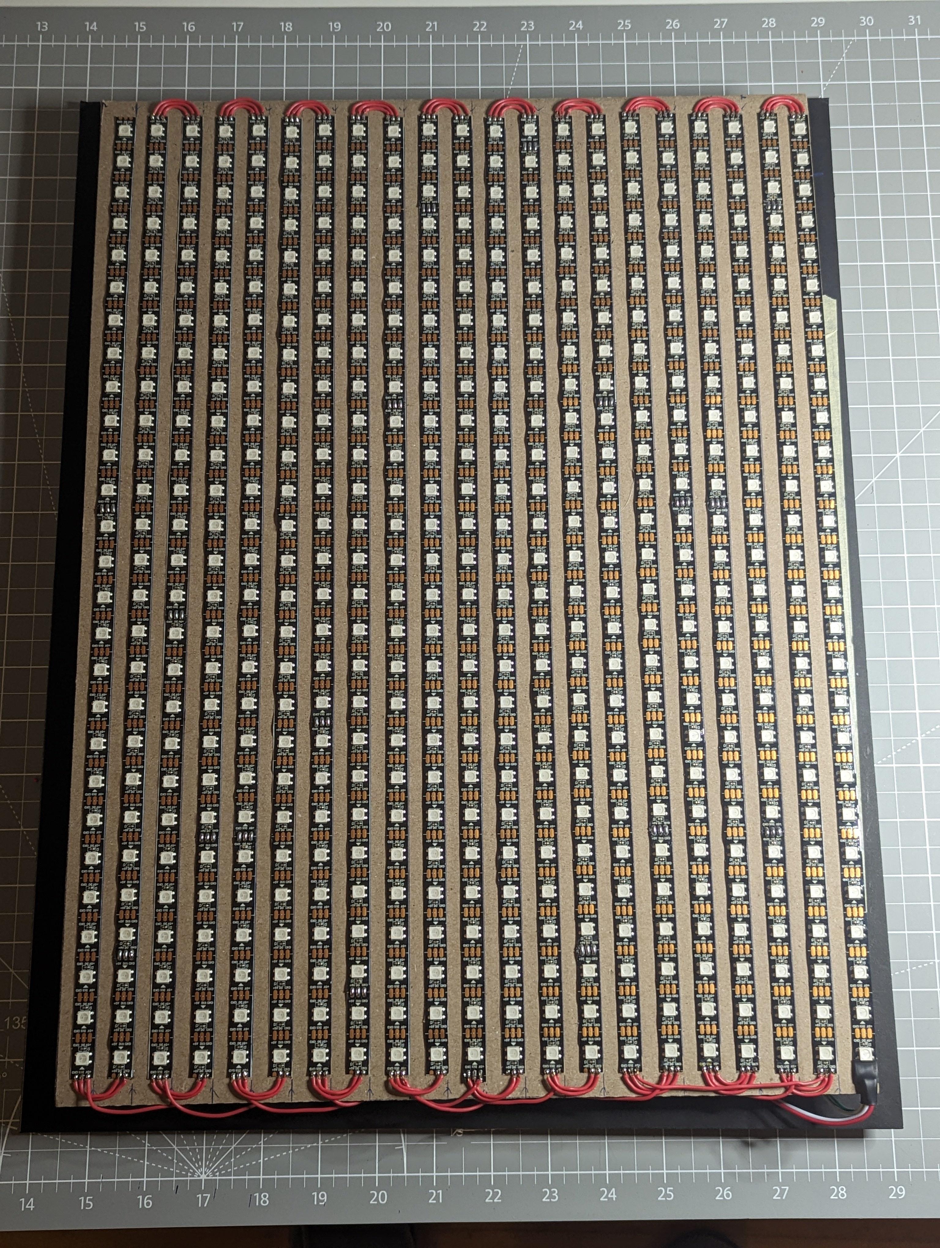
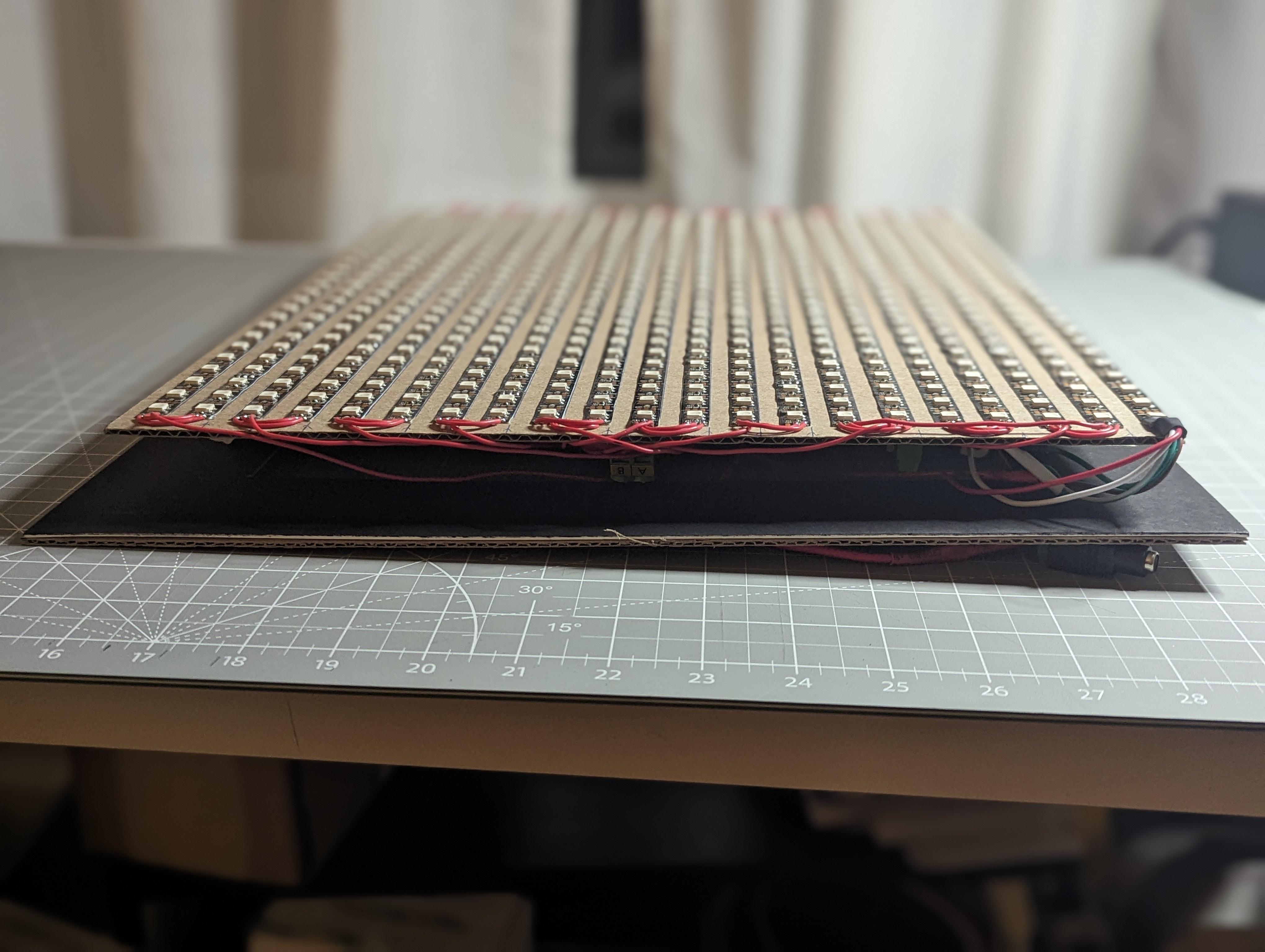
Most of the work went into the physical build. Every LED and electrical connection was soldered by hand, which quickly became the most time consuming part of the project. Keeping rows aligned, avoiding cold joints, and fixing mistakes as they appeared forced me to slow down and work carefully.
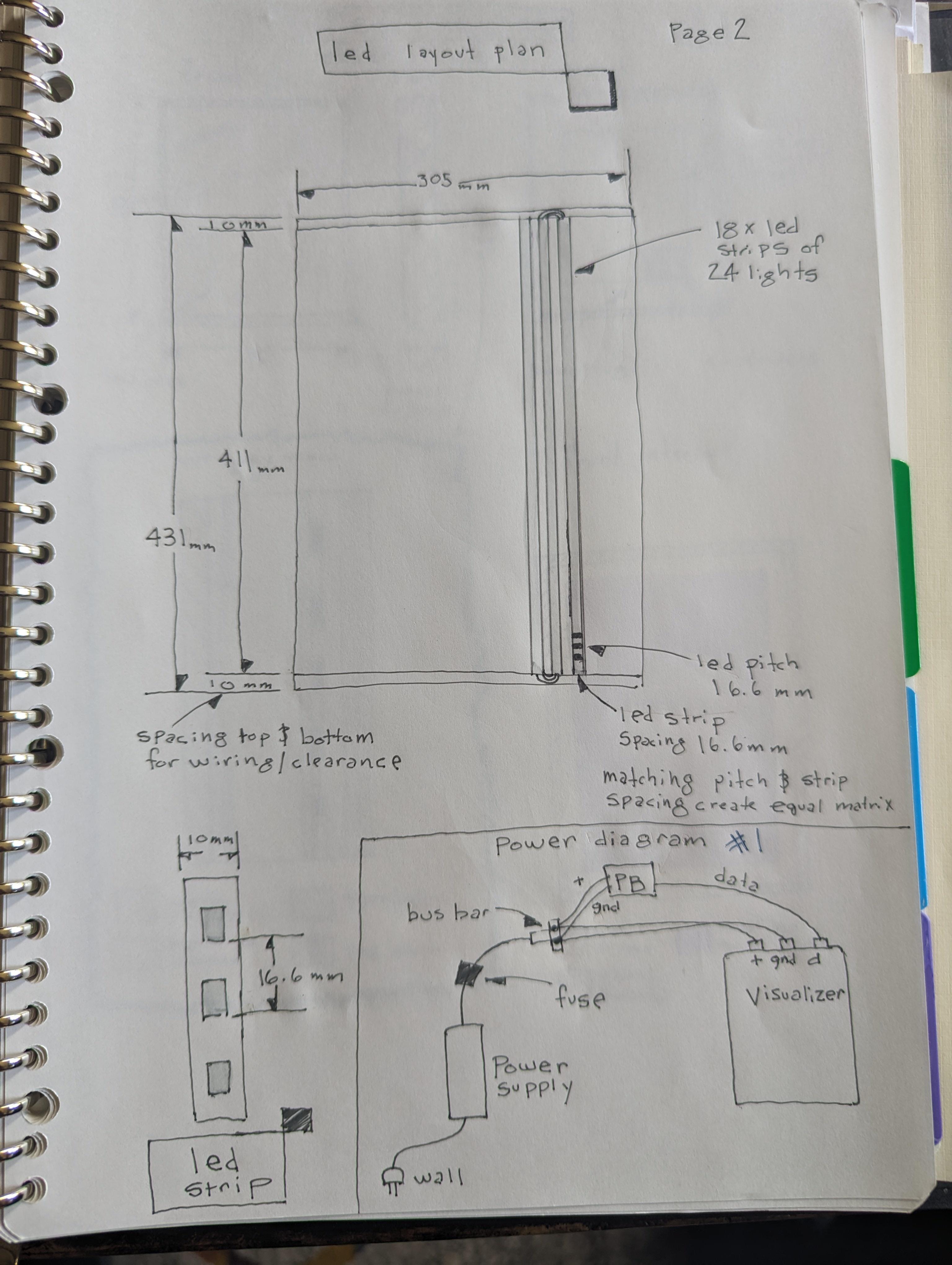
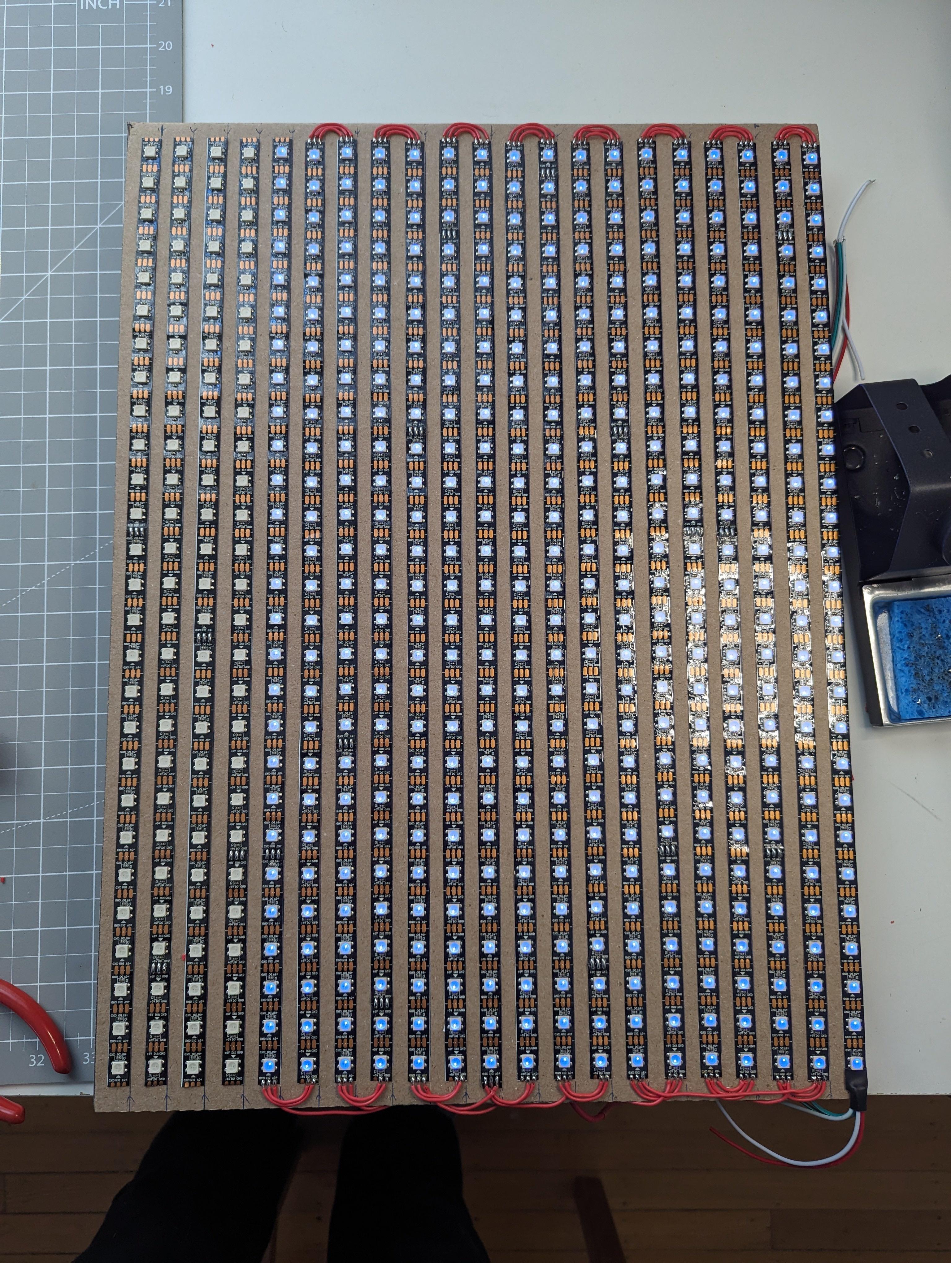
The matrix uses WS2812 addressable LEDs arranged in a vertical zig zag pattern. Because of the current requirements at scale, power is injected every other vertical column rather than relying on a single feed point. This significantly reduced voltage drop and kept color consistency across the display.
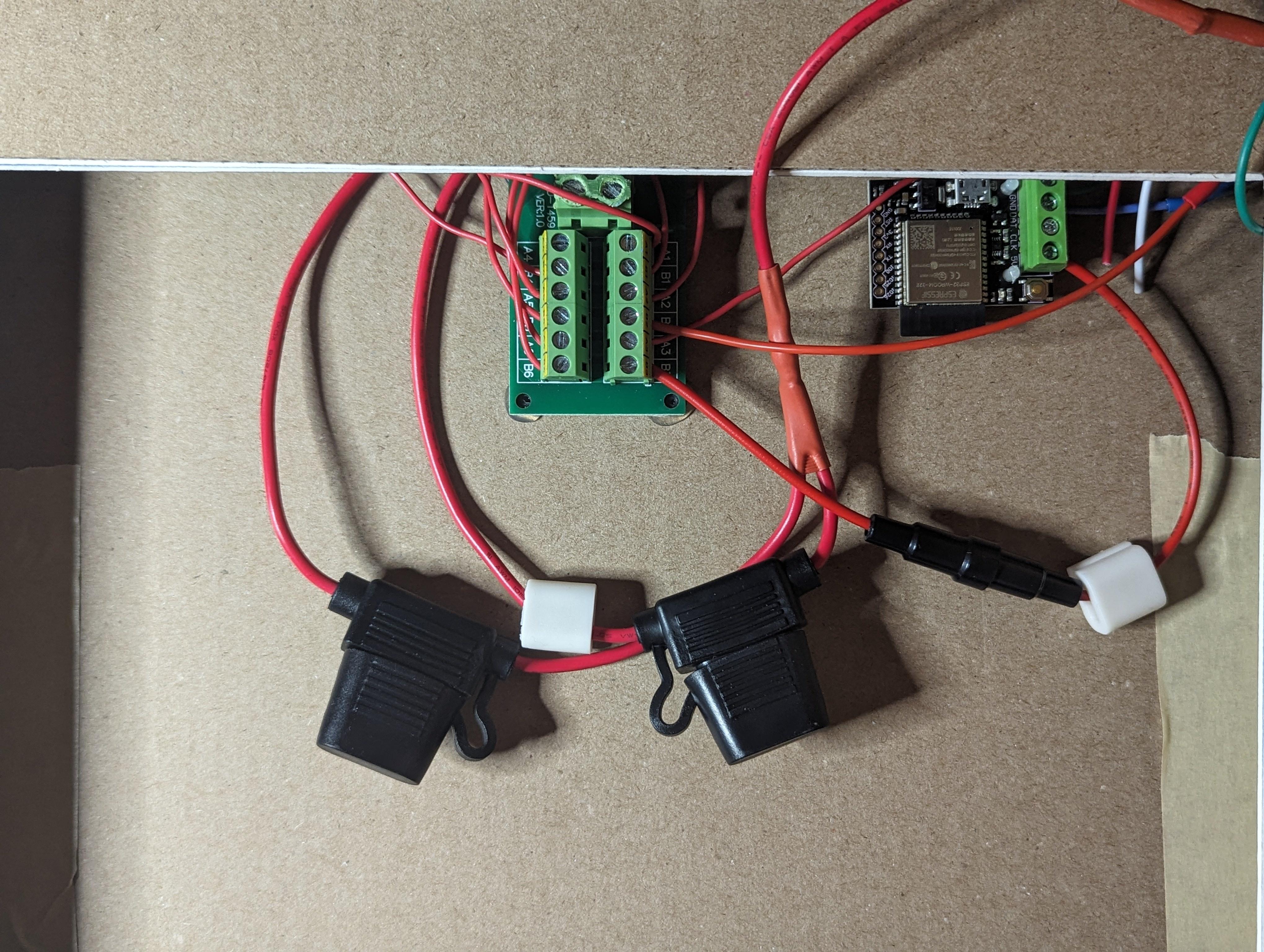
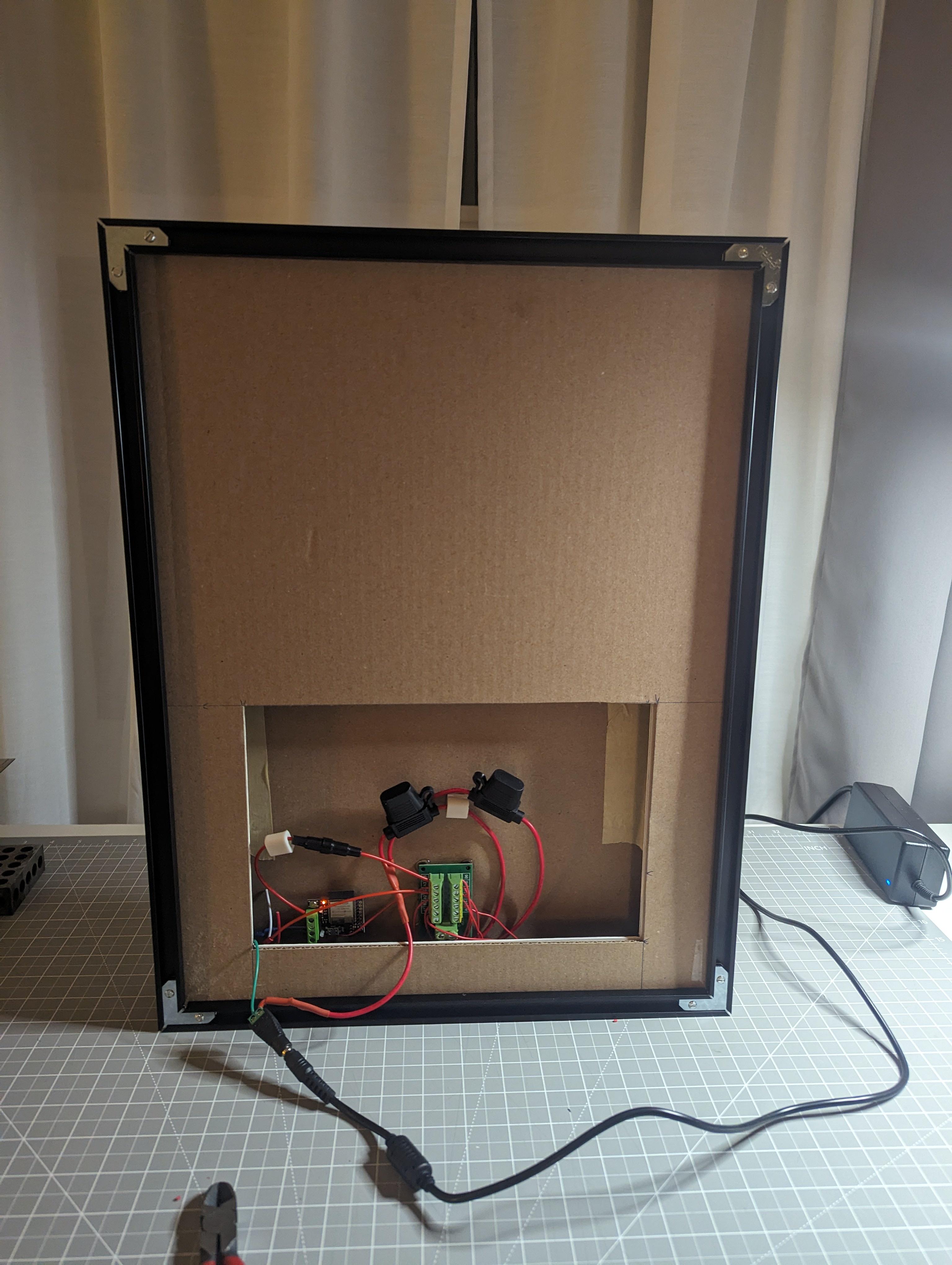
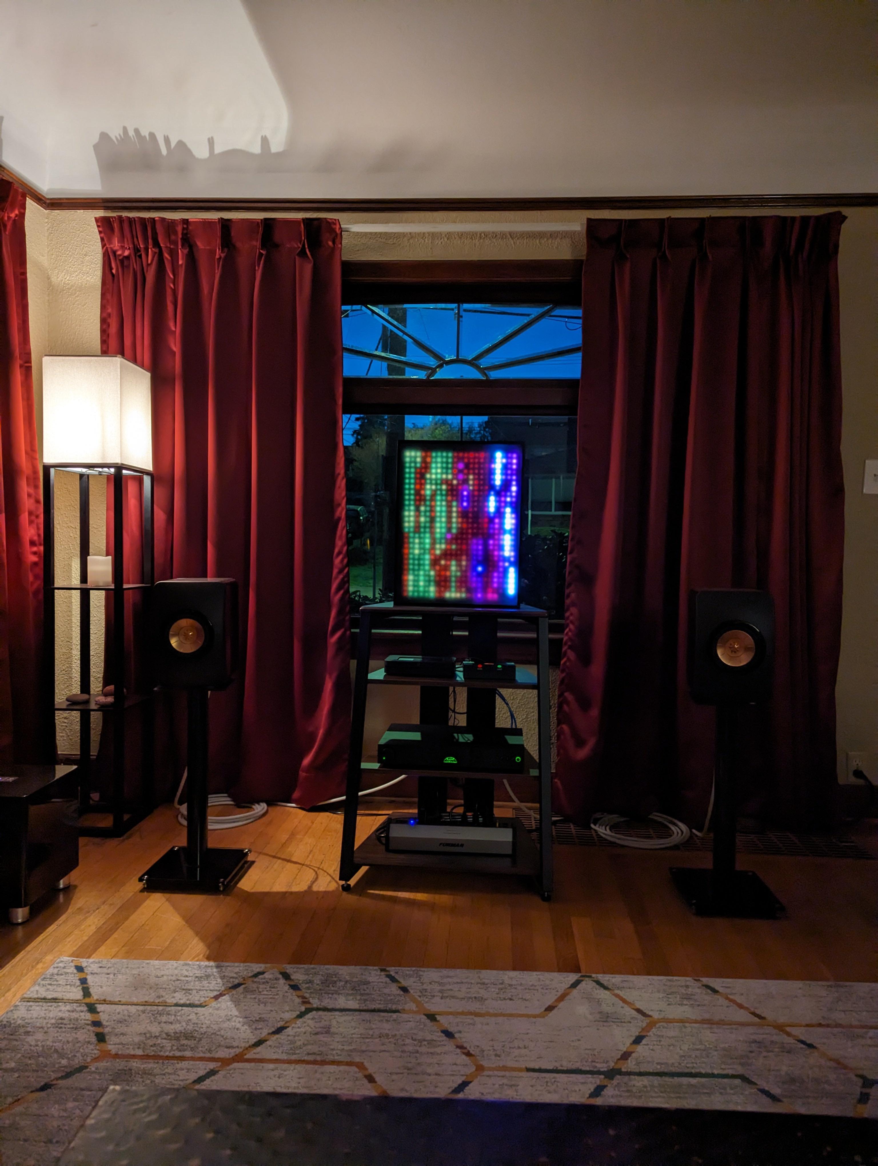
Power distribution became a major learning experience. As the matrix grew, issues like voltage drop and current limits stopped being abstract concepts and turned into real problems that affected whether the system worked at all. To address this, I used a 20 amp fanless AC to DC power supply mounted behind the matrix and connected via a standard barrel connector.
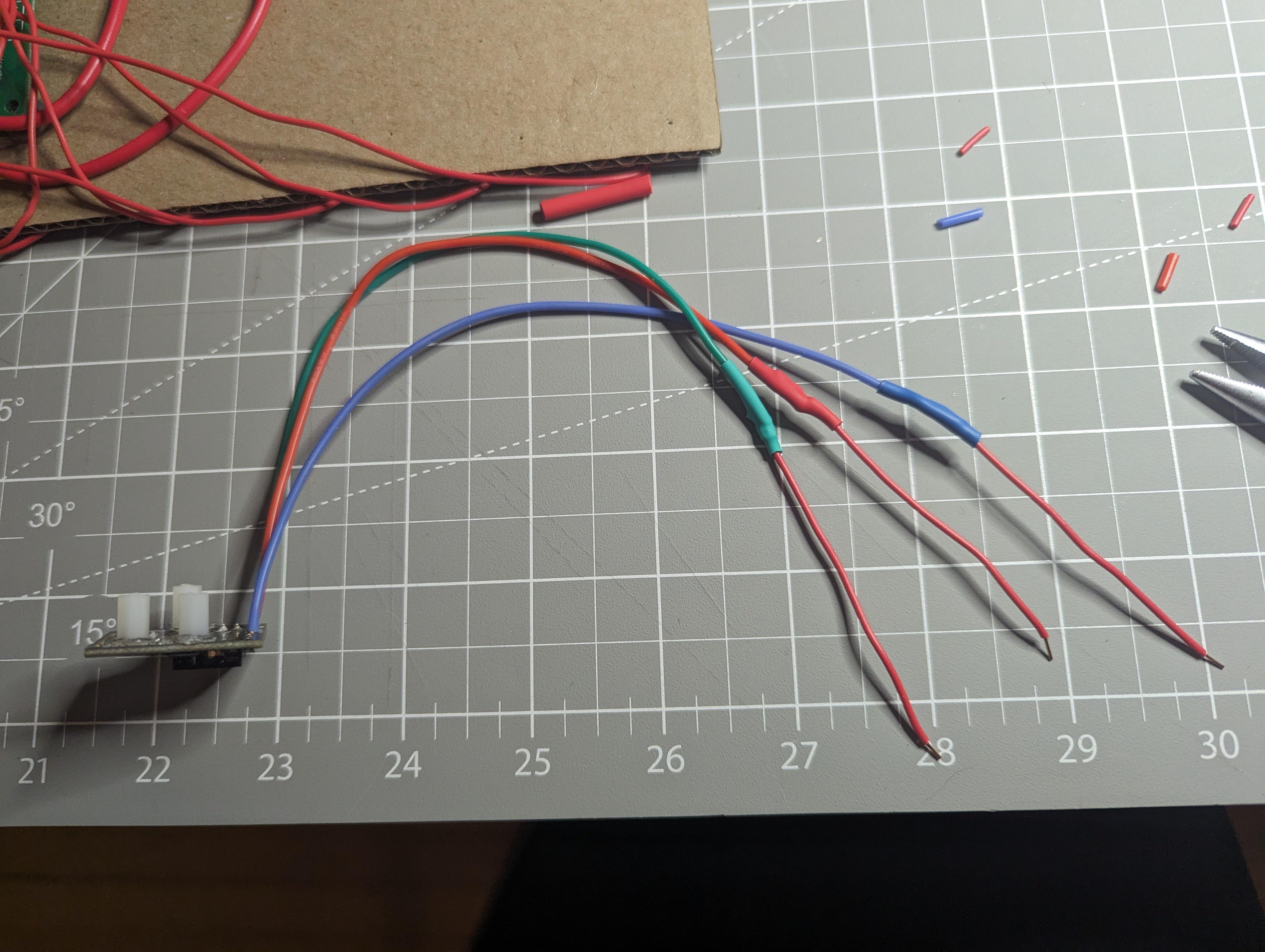
To protect the system, I added multiple layers of safety. Inline tube fuses are used alongside 5 amp automotive blade fuses to ensure no single section can overload. On the software side, I hard limited the global brightness to 72 percent so the matrix never attempts to draw more power than the supply can safely deliver, even under worst case scenarios.
Mapping the LEDs in Software
Once the hardware layout was locked in, I needed a reliable way to map physical LED positions to logical coordinates. Because the LEDs are wired in a zig zag pattern, a straight linear mapping would not work.
I solved this by generating a custom coordinate map that accounts for alternating column direction. Even numbered columns count top to bottom, while odd numbered columns reverse direction. This allows animations to be written in simple x and y space without caring about wiring direction.
This is the exact mapping function I used:
function(pixelCount) { var width = 21; var height = 27; var map = [];
for (var x = 0; x < width; x++) { for (var y = 0; y < height; y++) { var i = x % 2 == 0 ? (x * height + y) : (x * height + (height - 1 - y)); map[i] = [x, y]; } }
return map; }
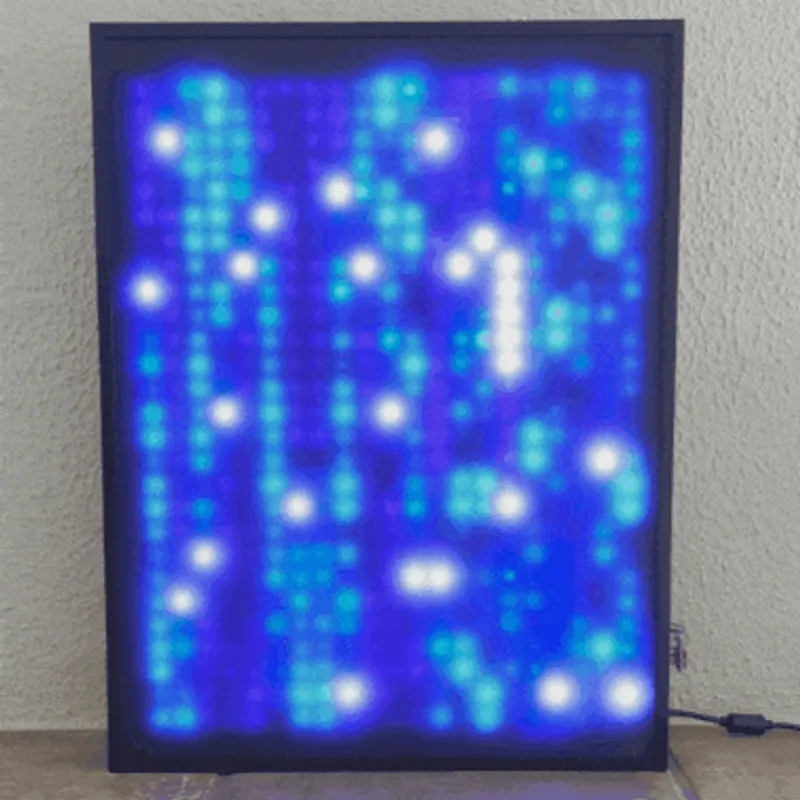
Once this mapping was in place, writing animations became far more intuitive. Effects could be described in terms of position and motion rather than individual LED indices, which made experimentation much faster.
Making the Matrix Come Alive With Software
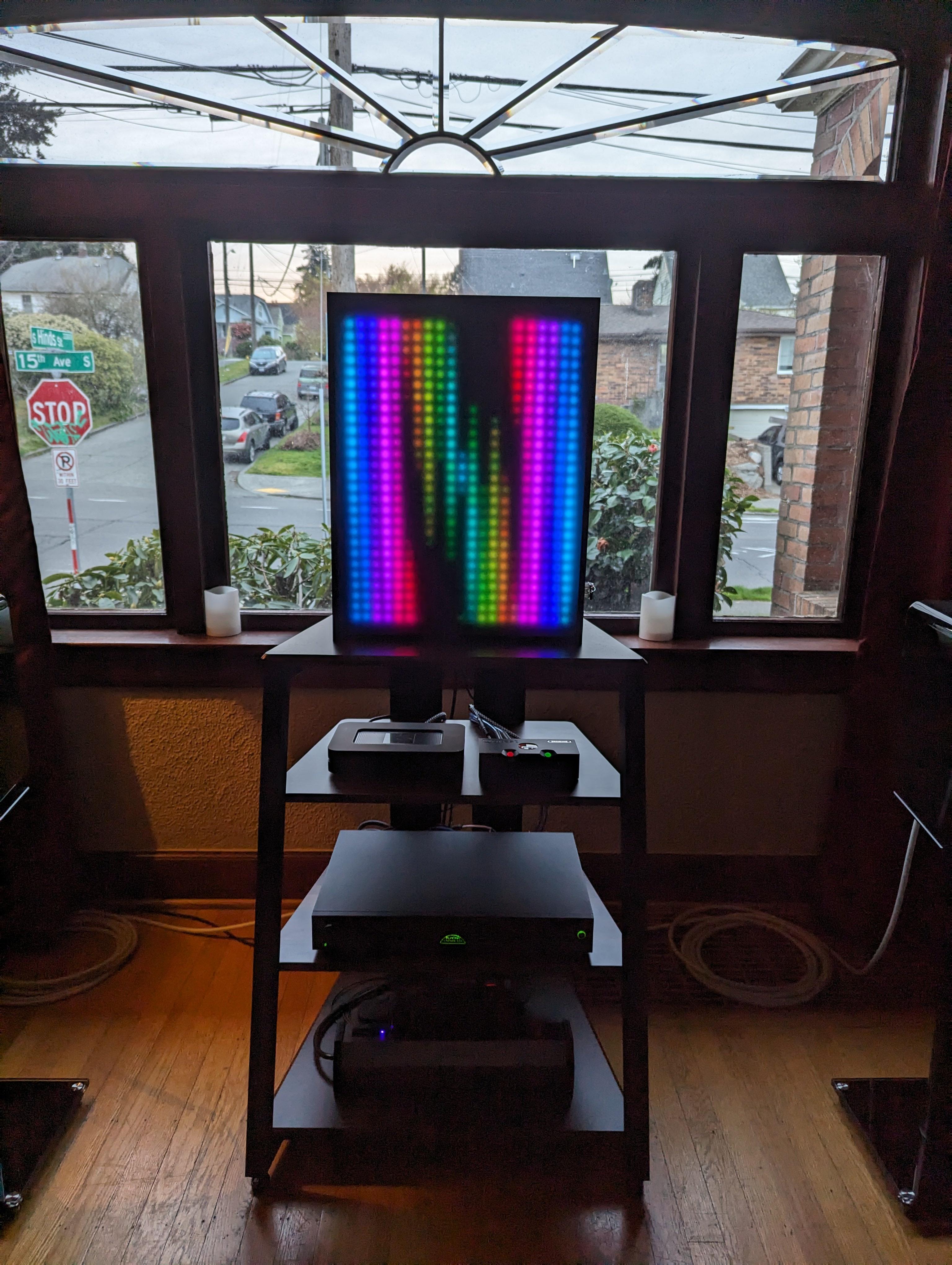
With the hardware stable and the mapping solved, the focus shifted to software. I used JavaScript to drive animations and manage data updates across the matrix. Writing patterns that look good on a computer screen is one thing. Writing patterns that look good on a large physical grid of LEDs is very different.
Refresh timing, update order, and animation pacing all had a noticeable impact on how smooth or harsh effects appeared. Many animations went through several iterations before they felt right. This part of the project involved a lot of trial, error, and small adjustments that only made sense once I could see the results in real space.
Adding Remote Control Through a Web Interface
One of the most rewarding additions was a simple web based interface. I wanted to control the matrix without plugging into it directly, so I built a local interface that works from a phone or any browser on the network.
This pushed the project beyond hardware alone and into networking and user interface work. The goal was not to make something flashy. It was to make the system usable. Being able to change patterns, tweak parameters, or shut things down remotely made the project feel complete in a way it had not before.
Why This Project Was Worth Building
What I enjoy most about this project is that it did not stop being interesting once it was finished. I still find myself tweaking animations, refining power limits, and rewriting sections of code as I learn more.
More than anything, this build showed me how much depth exists at the intersection of hardware and software. It reinforced that learning comes from debugging real problems, making mistakes, and gradually turning a rough idea into something reliable and well understood.
This LED matrix is not just a display. It is a record of what I learned and a platform I can keep improving.
Reference Images